





Skip to content
ZZ STEEL ZZ STEELPOWER INFRASTRUCTURE

Load Calculation

Accurate Analysis. Reliable Design. Safe Performance.

Accurate load analysis provides the foundation for safe and economical transmission line, steel pole and substation structure design.

Ensure SafetyOptimize DesignComply StandardsAdvanced Analysis
Ensure SafetyReliable under all loads
Optimize DesignEconomical solutions
Comply StandardsInternational codes
Advanced AnalysisProfessional methods

Load Types Considered

All actions expected during construction and service life are evaluated.

Dead Load (DL)

Dead Load (DL)

Self-weight of structures, crossarms and accessories.
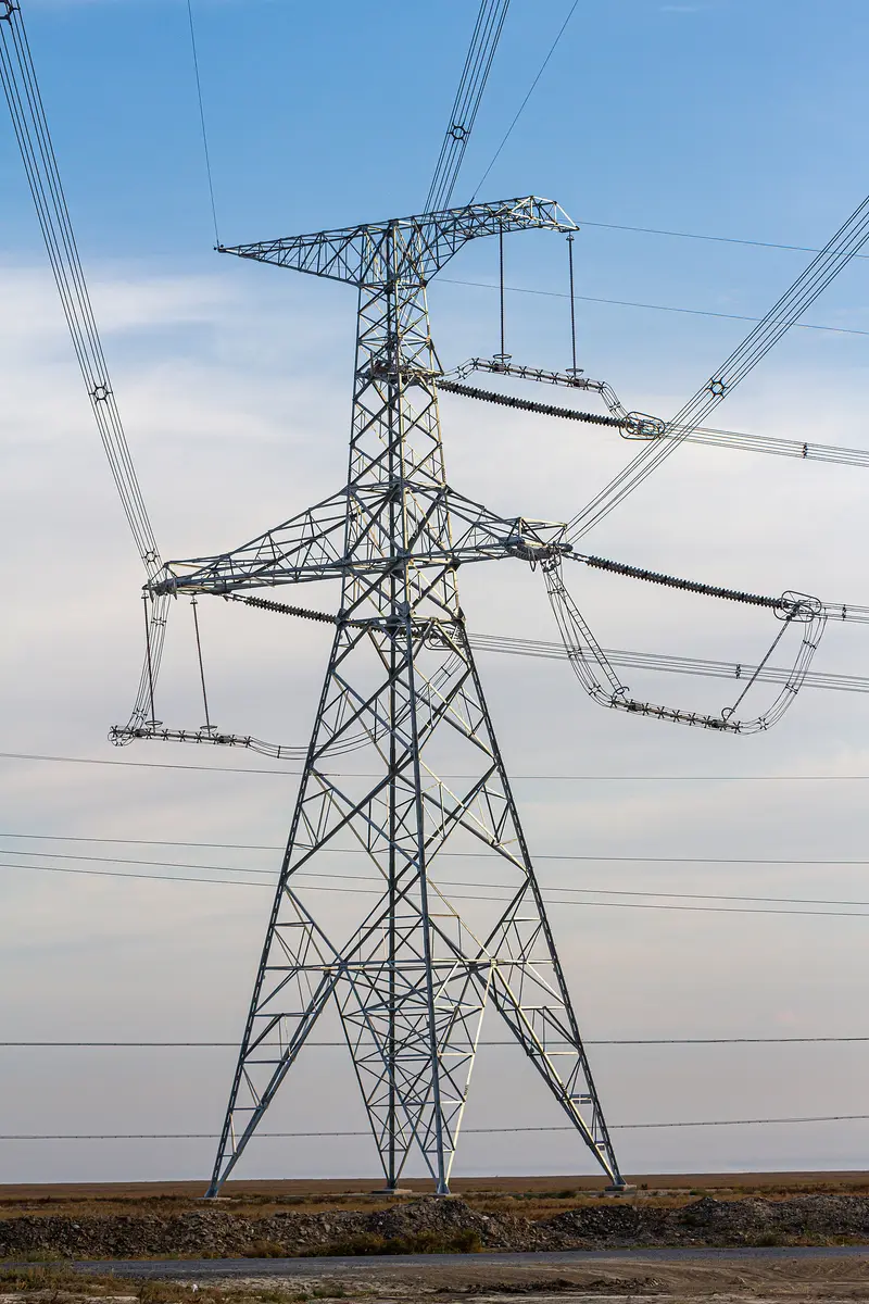
Conductor Load (LL)

Conductor Load (LL)

Conductors, shield wires, insulators and fittings.
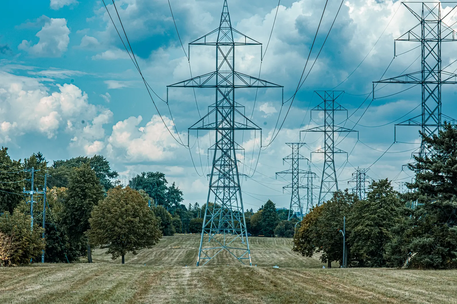
Wind Load (WL)

Wind Load (WL)

Wind pressure on structures and line components.
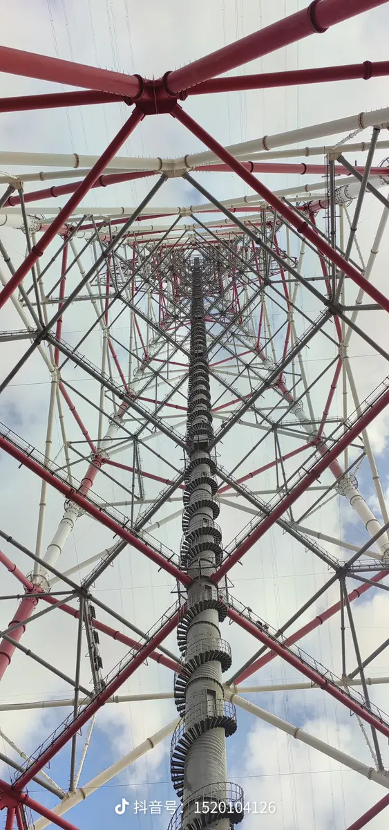
Ice Load (IL)

Ice Load (IL)

Ice accretion on conductors and structures.
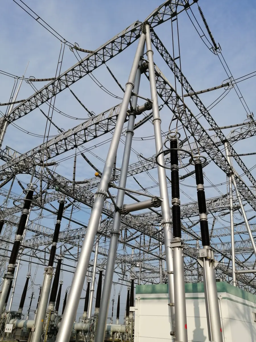
Seismic Load (EL)

Seismic Load (EL)

Earthquake effects by seismic zone and site class.

Temperature Load (TL)

Temperature Load (TL)

Member forces from temperature variation.
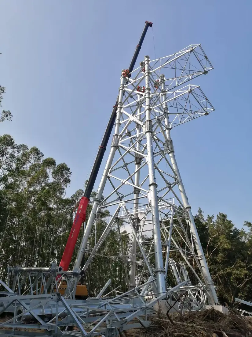
Construction Load (CL)

Construction Load (CL)

Temporary loads during erection.

Load Calculation Workflow

A transparent, review-driven process from project input to final delivery.

01Data CollectionSite and project parameters
02Load InputDefine code-based actions
03Load CombinationStrength and stability cases
04AnalysisAdvanced structural software
05Result CheckForces, displacement and utilization
06Report OutputCalculation report and design basis

Calculation Methods

  • Equivalent static analysis for regular structures
  • Dynamic analysis for complex wind or seismic response
  • Strength, stability and serviceability checks
  • Time-history or response-spectrum methods where required
  • Independent result review and verification

Calculation Software

  • SAP2000
  • ETABS
  • STAAD.Pro
  • ANSYS
  • PLS-CADD
  • Project calculation spreadsheets
0.87Maximum Utilization
95.4 mmTop Displacement
412.6 kNMaximum Base Shear
SAFE220kV Example Result
Standards & Software
IEC 60826ASCE 10GB 50545ANSI 360EN 1993

220kV Angle Tower — Load Summary

Reference values from customer-provided technical content; actual results vary by project.

Load TypeDescriptionResultStatus
DLDead Load152.6 kNChecked
LLConductor Load96.3 kNChecked
WLWind Load287.4 kNChecked
ILIce Load148.7 kNChecked
ELSeismic Load135.2 kNChecked
TLTemperature Load±32.5 kNChecked

Full Technical Scope

Complete technical content converted from the client’s second-edition Word material for this page.

LOAD CALCULATION

  • Accurate Analysis. Reliable Design. Safe Performance.
  • Load calculation is the foundation of a safe and economical transmission line or substation structure design. Our engineering team performs accurate load analysis in accordance with international standards to ensure every structure has the strength and stability to perform in all conditions.

Core Advantages

  • Ensure Safety
  • Reliable structures under all loads.
  • Optimize Design
  • Economical and efficient solutions.
  • Comply Standards
  • Meet international codes and regulations.
  • Advanced Analysis
  • Professional tools and experienced team.

Design Objectives

  • Accurate Input
  • Accurate site data and parameters.
  • Precise Calculation
  • Advanced methods and tools.
  • Reliable Results
  • Safe, reliable and optimized design.

LOAD TYPES CONSIDERED

  • We consider all possible loads that may act on the structure during its service life.
  • Dead Load (DL)
  • Self-weight of tower, cross arms, foundations and accessories.
  • Conductor Load (LL)
  • Weight of conductors, shield wires, insulators and fittings.
  • Wind Load (WL)
  • Wind pressure on structure, conductors and shield wires.
  • Ice Load (IL)
  • Weight of ice accretion on conductors, shield wires and structures.
  • Seismic Load (EL)
  • Earthquake effects based on seismic zone and site class.
  • Temperature Load (TL)
  • Effects due to temperature variation on members.
  • Construction Load (CL)
  • Loads during erection and construction conditions.

LOAD CALCULATION WORKFLOW

  • 1. Data Collection
  • Collect project data, site conditions and design parameters.
  • 2. Load Input
  • Determine all load cases according to relevant standards.
  • 3. Load Combination
  • Generate load combinations for strength and stability.
  • 4. Analysis
  • Perform structural analysis using advanced software.
  • 5. Result Check
  • Check member forces, displacements and utilization ratios.
  • 6. Report Output
  • Provide calculation reports and design basis for manufacture.

LOAD CALCULATION METHODS

  • We use multiple calculation methods to ensure accuracy and reliability.
  • Equivalent Static Method
  • Widely used for transmission line structures
  • Simplified static force equivalent to dynamic effects
  • Suitable for most regular projects
  • In accordance with IEC, ASCE and GB standards
  • Dynamic Analysis Method
  • Consider dynamic effects such as wind and seismic
  • More accurate for complex or special structures
  • Time-history or response spectrum analysis
  • Ensure safety under extreme conditions

LOAD CALCULATION SOFTWARE

  • We use professional software to perform accurate structural analysis.
  • SAP2000
  • General structural analysis software for 3D modeling and load calculation.
  • ETABS
  • Specialized in building and substation structure analysis and design.
  • STAAD.Pro
  • Advanced structural analysis and steel structure design software.
  • ANSYS
  • Finite element analysis for complex structures and components.

EXAMPLE CALCULATION CASE — 220kV ANGLE TOWER

  • Project Parameters
  • Voltage Level:
  • 220kV
  • Tower Type:
  • Angle Tower
  • Height:
  • 38.6 m
  • Design Standard:
  • IEC 60826
  • Basic Wind Speed:
  • 25 m/s
  • Ice Thickness:
  • 10 mm
  • Seismic Zone:
  • Zone 2
  • Importance Factor:
  • 1.0

Load Summary (Ultimate Combination)

  • Load Type Description Result
  • DL Dead Load 152.6 kN
  • LL Conductor Load 96.3 kN
  • WL Wind Load 287.4 kN
  • IL Ice Load 148.7 kN
  • EL Seismic Load 135.2 kN
  • TL Temperature Load ±32.5 kN

Analysis Result

  • Maximum Member Utilization:
  • 0.87
  • Maximum Displacement (Top):
  • 95.4 mm
  • Maximum Base Shear:
  • 412.6 kN
  • Tower Status:
  • ✔ Safe
  • All member utilizations are within allowable limits. The structure meets strength, stability and serviceability requirements.

DESIGN STANDARDS

  • We perform calculations in accordance with major international standards.
  • IEC 60826
  • ASCE 10
  • GB 50545
  • ANSI 360
  • EN 1993 / 1999
  • More

WHY CHOOSE ZZ STEEL

  • Experienced Engineers
  • Professional team with rich experience in load calculation and design.
  • Accurate & Reliable
  • Strict calculation process ensures accurate and reliable results.
  • Advanced Tools
  • Using industry-leading software and analysis methods.
  • Compliant Standards
  • Comply with international standards and customer requirements.
  • Optimized Solutions
  • Optimize design to reduce material usage and total project cost.
  • Full Support
  • Provide professional support from design to delivery and installation.

Accurate Analysis. Reliable Design. Safe Performance.

Share your project requirements with our engineering and sales team.

Get a quote →